
1. Introduction: Why I Built the XhtCore Board
The XhtCore project started as a personal effort to revisit the Allwinner F1C200S SoC, organize what I had learned about the chip, and turn that knowledge into an open-source hardware project that others could study and build upon.
The original idea was straightforward: design a development board, document the hardware design process, and share the results with the community. Rather than simply publishing PCB files, I wanted to explain the engineering decisions behind the design, including schematic review, PCB layout, power integrity, signal routing, and other details that are easy to overlook when building a board from scratch.
As the project progressed, however, the amount of work involved became much greater than I had initially expected.
By the time the PCB design was nearly complete, I still needed to review the schematics and carefully inspect the layout. Even seemingly small details required attention: the 3W routing principle, reference-plane continuity, differential-pair length matching, antenna impedance, and numerous other layout considerations.
Because I intended to explain the design to other people, I did not want to publish the files without first checking the details as thoroughly as I could.
At the same time, personal circumstances made it difficult to maintain momentum. In October 2023, I found myself struggling with the project, and by November, I had temporarily stopped opening my EDA software altogether. For someone who had been working on the board almost every day, that was a significant change.
Things gradually improved in December. I returned to the project, completed the hardware design, and recorded a video explaining the board.
The software tutorials, however, remained unfinished as other commitments took priority.
Looking back, this project represents more than just a PCB design. It is also a record of learning, experimentation, setbacks, and the process of bringing a hardware project to completion.
I am sharing the XhtCore project so that other developers can explore the F1C200S and F1C100S platforms, examine the hardware implementation, and use the design as a reference for their own embedded systems projects.
2. Project Overview
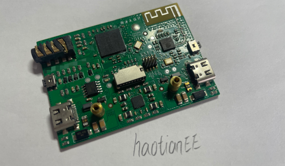
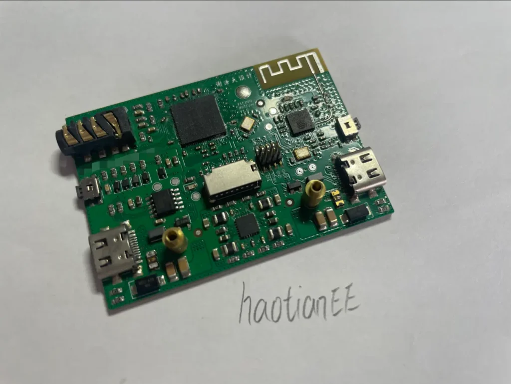
The XhtCore is an open-source development board built around the Allwinner F1C200S / F1C100S family of application processors.
It combines the main processor with power-management circuitry, a USB-to-UART interface, a Wi-Fi module, display connectivity, SD card storage, and an audio interface. These components make the board a useful starting point for exploring embedded hardware design and Linux-oriented development.
Illustrative reference images of the types of components used in the project. These are not verified photographs of the actual XhtCore board.
Key Hardware Specifications
| Component | Specification |
|---|---|
| Main processor | Allwinner F1C200S / F1C100S |
| USB-to-UART bridge | CH340K |
| DC-DC power supply | EA3059 |
| Wi-Fi | ESP8266EX |
| Display | GMT02401 |
| Removable storage | 1 × SD card slot |
| Audio | 1 × audio interface |
| Hardware design | Custom PCB |
| Project files | Open-source repository on GitHub |
The table above reflects the component information provided in the original project description. For exact electrical specifications, supported display modes, power requirements, and interface pin assignments, please consult the project’s schematics and component datasheets.
3. Main Processor: Allwinner F1C200S / F1C100S
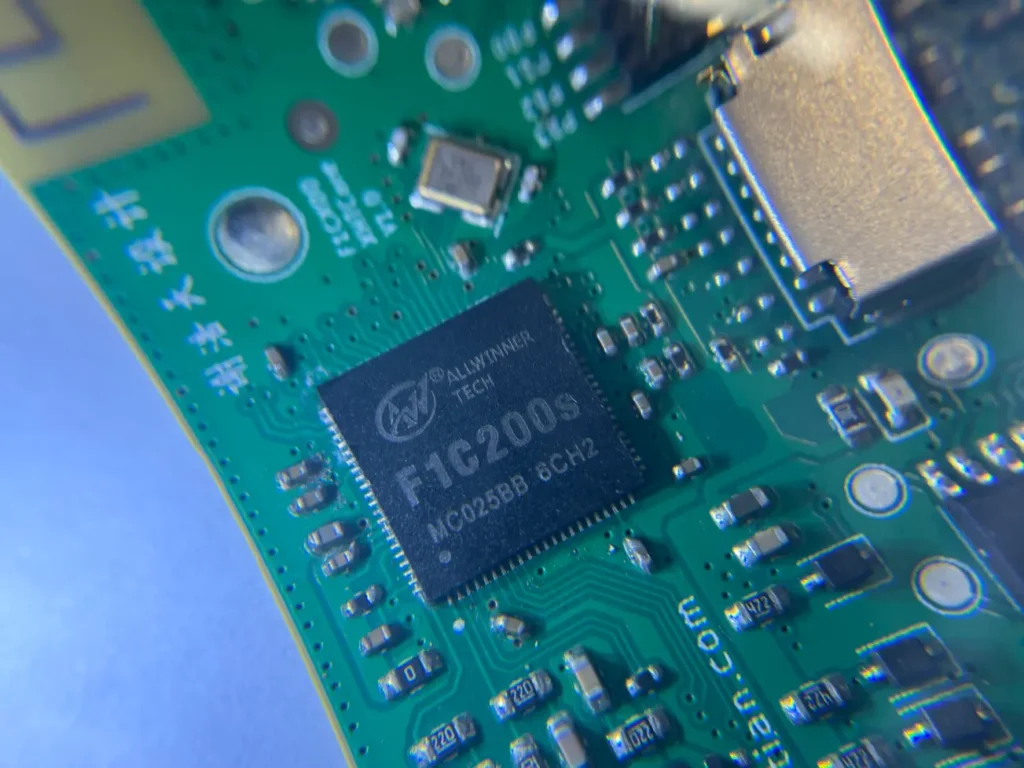
At the heart of the XhtCore board is the Allwinner F1C200S or its related F1C100S variant.
These processors are of interest to embedded developers looking for a compact platform for low-cost multimedia devices, small display systems, and Linux-based embedded applications.
Working with this processor family provides an opportunity to explore several layers of embedded development:
- Hardware design: processor power supplies, reset circuitry, clocking, decoupling, and peripheral connections.
- Boot and firmware: understanding the boot process, storage requirements, and the relationship between the bootloader and operating system.
- Embedded Linux: investigating kernel configuration, device trees, peripheral drivers, and root filesystem construction where supported by the software stack.
- Peripheral integration: connecting storage, displays, serial debugging interfaces, audio circuitry, and external communication modules.
For developers learning embedded Linux, a board like XhtCore can help connect theoretical knowledge with practical hardware work.
It is important to distinguish between the capabilities of the processor itself and those implemented on the finished board. The availability of a particular peripheral, driver, or software feature depends on the board circuitry, the relevant pin connections, and the software support provided by the project.
4. Hardware Design and Major Components
4.1 USB-to-UART Debug Interface — CH340K
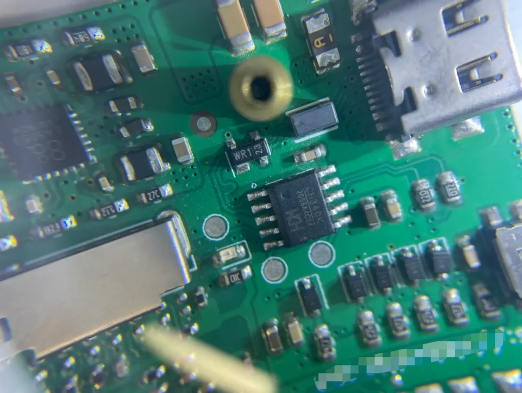
The board uses the CH340K as its USB-to-UART bridge.
A serial console is one of the most useful tools when bringing up a new embedded Linux board. It can provide access to bootloader output, kernel messages, and command-line interaction, depending on the firmware and the way the UART interface is connected.
For hardware developers, a working serial connection can make the difference between debugging a visible software error and trying to diagnose a system that appears completely unresponsive.
When using the serial interface, check the following:
- Confirm the correct UART port and pin assignments from the schematic.
- Verify the signal voltage levels before connecting an external adapter.
- Make sure the transmit and receive signals are connected correctly.
- Confirm the baud rate and terminal settings required by the firmware.
- Check the board’s grounding and power connections if the serial output is unstable.
The CH340K is the USB-to-serial interface component; it should not be confused with a USB host controller or a USB-to-storage interface.
4.2 Power Supply — EA3059
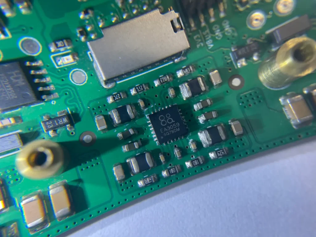
Power-supply design is one of the most important parts of any embedded hardware project.
The XhtCore design lists the EA3059 as its DC-DC power component. The regulator’s exact output configuration and the rails it supplies should be verified against the schematic and the relevant datasheet.
A reliable power design requires more than selecting a regulator with an appropriate nominal output voltage. Developers also need to consider:
- Input-voltage range and expected load current.
- Output-voltage accuracy and transient response.
- Input and output capacitor selection.
- PCB placement of the regulator and its associated components.
- Switching-current loops and their effect on noise.
- Ground return paths and separation of sensitive analog circuitry where appropriate.
- Thermal performance under realistic operating conditions.
During board bring-up, measure the relevant supply rails before connecting or powering sensitive components. If the board behaves unexpectedly, checking the power rails under load is often a more productive first step than immediately investigating the software.
These are general hardware validation recommendations, not a claim that the XhtCore board has undergone a particular set of power-integrity tests.
4.3 Wi-Fi Connectivity — ESP8266EX
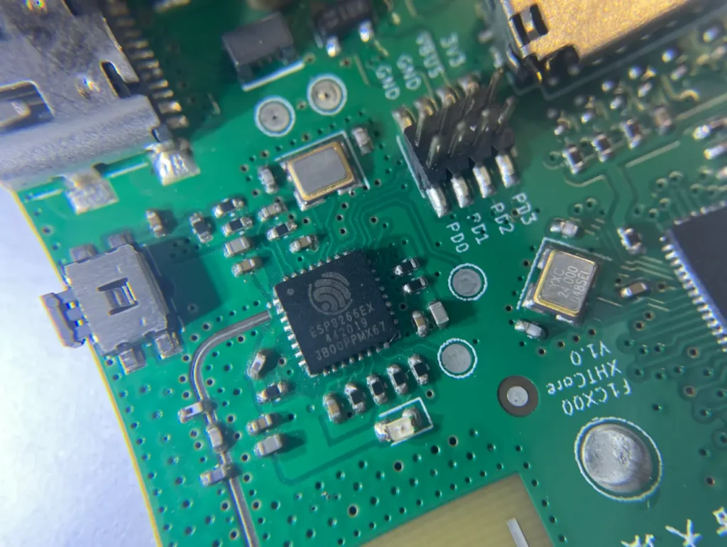
The board includes the ESP8266EX for Wi-Fi-related functionality.
A wireless companion chip can extend the possibilities of a compact embedded system, allowing it to participate in networked applications when the required firmware and host-side integration are implemented.
Potential areas for experimentation include:
- Wireless telemetry and status reporting.
- Network-connected embedded devices.
- Remote monitoring and control.
- Communication between an embedded Linux host and an external wireless subsystem.
The precise communication method between the main processor and the ESP8266EX must be confirmed from the schematic and software implementation. Likewise, the presence of the Wi-Fi chip alone does not guarantee that wireless networking is already configured or operational.
For PCB designers, RF layout deserves particular attention. Antenna placement, impedance matching, ground-plane geometry, nearby copper, and surrounding components can all influence wireless performance.
The original project description mentions antenna impedance as one of the layout details that required attention. This is a useful reminder that RF circuitry needs to be reviewed as a complete electrical and physical system, rather than treated as an ordinary digital signal connection.
4.4 Display Interface — GMT02401
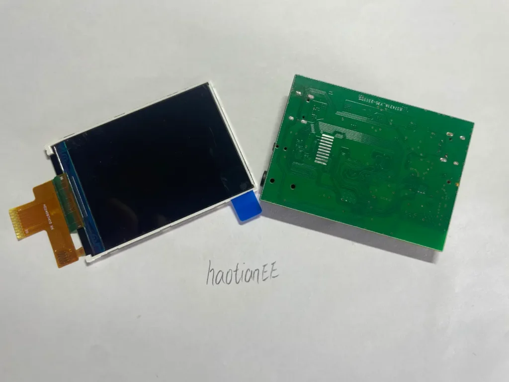
The project lists the GMT02401 as its display.
A display interface is useful for experimenting with graphical user interfaces, status screens, lightweight multimedia applications, and embedded user-interface design.
When bringing up a display, several elements need to work together:
- Correct power and signal connections.
- The display’s supported resolution and timing requirements.
- Appropriate pin multiplexing and controller configuration.
- Backlight control, where applicable.
- Software support in the bootloader, kernel, or application layer.
The exact display interface, resolution, color format, and backlight circuit should be checked against the XhtCore schematic and the display documentation before attempting to configure a driver.
If display output does not work as expected, verify the power supply and hardware connections first, then inspect the relevant software configuration and initialization sequence.
4.5 SD Card Storage
The board includes one SD card slot.
Removable storage is particularly convenient during embedded Linux development because it can provide a practical way to store boot-related files, operating-system images, or application data, depending on the board’s boot configuration and software support.
It can also simplify experimentation: developers can prepare a card on a separate computer, insert it into the board, and test different software configurations without modifying the PCB.
However, the presence of an SD card slot does not establish which boot modes or storage layouts are supported. Those details depend on the processor’s boot configuration, the board’s wiring, and the available firmware.
4.6 Audio Interface
An audio interface is also included in the hardware design.
Audio functionality can provide another useful area for experimentation, from basic signal routing to embedded multimedia applications.
The actual capabilities depend on the audio circuitry, codec configuration, signal routing, and software support. Developers interested in audio should inspect the schematic to identify the relevant analog and digital connections before attempting playback or recording.
Analog audio circuits also benefit from careful grounding, power-supply decoupling, and PCB layout practices that reduce interference from switching regulators and high-speed digital signals.
5. PCB Layout: Small Details Matter
One of the main lessons from the XhtCore project is that completing a schematic is only one part of designing a reliable PCB.
As I reviewed the board, I found that the later stages of layout required considerable attention to detail. Even after the major components and connections were in place, there were still questions to review and decisions to validate.
Illustrative PCB layout references. Use actual XhtCore EDA screenshots in this section for project-specific technical evidence.
5.1 The 3W Routing Guideline
The 3W rule is a common PCB routing guideline used to reduce coupling between adjacent traces.
In a simplified interpretation, the spacing between neighboring traces is designed in relation to the trace width. The exact convention used should be stated clearly in the design documentation.
It is not a universal guarantee of signal integrity. The required spacing depends on factors such as stack-up, dielectric properties, trace geometry, edge rates, and the acceptable level of coupling.
For practical designs, use the 3W guideline as an initial routing consideration rather than a substitute for detailed analysis.
5.2 Continuous Reference Planes
High-speed signals need suitable return-current paths. A continuous reference plane can help reduce loop area and control electromagnetic emissions.
When routing signals across a PCB, avoid unintentionally forcing return currents around splits or gaps in their reference planes. Such discontinuities can affect signal integrity and electromagnetic compatibility.
This becomes particularly important when a board contains switching power supplies, fast digital interfaces, or RF circuitry.
5.3 Differential-Pair Length Matching
Differential signaling is used by interfaces that transmit information over paired conductors.
Where the relevant interface requires length matching, routing should follow its actual electrical timing budget and design specifications. Matching trace lengths is not enough by itself: impedance control, pair spacing, reference-plane continuity, and routing symmetry can also matter.
It is equally important not to apply differential-pair rules indiscriminately to signals that are not part of a differential interface.
5.4 RF Impedance and Antenna Layout
Wireless circuitry introduces a different set of constraints.
Antenna feeds and RF transmission lines may require controlled impedance, depending on the design. Their geometry must be consistent with the PCB stack-up and the antenna’s electrical requirements.
Nearby copper, ground clearances, component placement, and the physical environment around the antenna can influence performance.
For this reason, RF layout should be reviewed against the relevant reference design and antenna documentation, rather than judged solely by whether the traces appear neat.
5.5 Schematic Review and Design Verification
Before publishing an open-source hardware project, it is worth checking both the schematic and the PCB layout.
A useful review process includes verifying component values and footprints, confirming power connections, checking connector pinouts, reviewing signal assignments, inspecting routing and return paths, and comparing critical circuits against datasheets or reference designs.
The goal is not to claim that a board is flawless. It is to make the design process transparent enough that other developers can understand the decisions, reproduce the design, and identify areas that may need improvement.
6. Hardware Bring-Up: A Practical Starting Point
For anyone planning to reproduce or adapt the XhtCore hardware, a staged bring-up process is a sensible approach.
Step 1 — Inspect the assembled board
Check component orientation, solder joints, connector placement, and any visible shorts before applying power.
Step 2 — Verify the power rails
Measure the supply voltages and confirm that they remain within the expected limits. Check for abnormal current draw or overheating.
Step 3 — Establish serial debugging
Confirm the UART pinout, logic voltage, baud rate, and terminal settings. Use the serial console to observe startup output if supported.
Step 4 — Test peripherals individually
Once the board starts reliably, validate storage, display output, audio, and wireless functionality one at a time.
This sequence is a general recommendation for embedded-board bring-up, not a report of completed test results for every XhtCore subsystem.
Keeping notes of measured voltages, startup logs, hardware revisions, and software versions can make troubleshooting much easier. These records also improve the quality of the project documentation for anyone who wants to reproduce the results.
7. Open-Source Hardware and Project Files
The hardware project is available on GitHub:https://github.com/xiehaotian2001/F1c200s_XhtCore
F1c200s_XhtCore
Xie Haotian · Open-source hardware project
The repository is the primary reference for the original design files and any additional materials published by the author.
Before building the board, check the repository for the available schematic files, PCB layout files, bill of materials, assembly notes, and any firmware or software resources.
Not every one of these resources is necessarily included, so verify the repository contents rather than assuming that a complete manufacturing and software package is available.
If you intend to modify or redistribute the design, also check the repository’s license and any component-specific licensing requirements.
Who Might Find This Project Useful?
The XhtCore design may be a useful reference for:
- Embedded hardware beginners who want to study the structure of a processor-based PCB.
- Electronics engineers interested in reviewing power, signal-routing, and RF design considerations.
- Embedded Linux learners exploring boot processes, peripheral integration, and device-driver development.
- Open-source hardware contributors looking for a starting point for experimentation and design improvements.
The project should be treated as a learning and engineering reference, not as a substitute for checking electrical specifications or validating a design for a particular product.
8. What Comes Next?
The original plan included software tutorials that would complement the hardware documentation. Although those tutorials were not completed at the time of writing the original article, there are several natural directions in which the project could be developed further.
Potential follow-up topics include:
- Reviewing the schematic block by block.
- Explaining PCB layout decisions with annotated EDA screenshots.
- Documenting the power-on and serial-debugging process.
- Exploring the processor’s boot sequence and supported boot media.
- Building and configuring a suitable embedded Linux software stack.
- Testing display, SD card, audio, and Wi-Fi functionality.
- Recording actual measurements and documenting known hardware limitations.
These are possible future documentation topics, not a claim that all of the associated features have already been tested or implemented.
For an open-source hardware project, even a small amount of reproducible test documentation can be valuable. Photos of the actual board, console logs, measured supply voltages, and verified peripheral tests provide readers with a much clearer understanding of what works and what remains to be explored.
9. Final Thoughts
The XhtCore project began as an effort to revisit the Allwinner F1C200S platform and share what I learned through hardware design.
The process turned out to be more demanding than I had anticipated. Reviewing schematics, checking PCB routing, and considering the many small details behind a working board took considerable time. Personal circumstances also interrupted the project, and the software documentation never progressed as far as I originally intended.
Nevertheless, the hardware design was completed, and I was able to record a video explaining the board.
I am publishing the project in the hope that it will be useful to other people studying embedded hardware and Linux development. If you find an issue, discover a better implementation, or build something based on this design, your feedback and contributions are welcome.
Open-source hardware is not only about sharing finished files. It is also about documenting the decisions, limitations, and lessons that make those files useful to other engineers.
Project repository: F1c200s_XhtCore on GitHub