
- Introduction
- 1. The Basic Idea: Connect First, Power On Later
- 2. Hardware Architecture
- 3. Wide-Input Power Architecture
- 4. 2.4GHz Wireless Control
- 5. MOSFET Power Switching
- 6. PCB Design
- 7. Firmware Programming and Assembly
- 8. Real-World Testing
- 9. Why Support Both 12V and 24V?
- 10. What This Modification Actually Sol the main output disabled while the clamps are being connected, the design aims to reduce the possibility of arcing at the connection does not replace proper battery polarity protection, current protection, fusing, or other safety measures that a what makes these DIY electronics projects interesting. There is no need to turn every project into a commercial product. Sometimes it is simply fun to noticeves
- 11. Conclusion
Introduction
If you regularly work on cars or keep a portable jump starter in your vehicle, you may have noticed a small but annoying problem with conventional jump starters.
Most portable jump starters use a very simple output design: the positive and negative leads are connected directly to a pair of alligator clamps. As soon as the clamps make contact with a vehicle battery, a spark can sometimes occur.
It may only be a brief flash, but it is not something I particularly like to see. Repeated arcing can leave burn marks on the battery terminals and contact surfaces, and in some situations it can potentially damage electrical or metal components.
I have been using and working with jump starters quite a bit recently, so I decided to see if this could be solved with a relatively simple hardware modification.
The idea is straightforward:
Connect the battery clamps first, then turn on the power remotely.
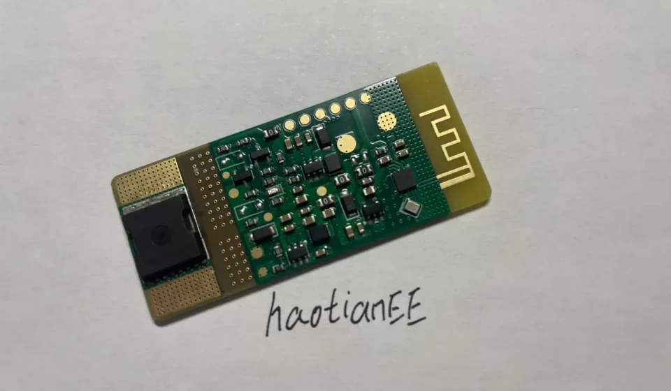
To achieve this, I designed a small 2.4GHz remote-controlled power switch board specifically for automotive jump starters.
The board uses a MOSFET as the main power switch and a Qinheng CH570 as the wireless controller. It is designed to work with both 12V and 24V vehicle systems, with an input range of approximately 7–24V.
This article covers the design concept, power architecture, wireless control, PCB design, assembly, and some real-world testing.
1. The Basic Idea: Connect First, Power On Later
The main problem with a conventional jump starter is that the output clamps are electrically live before they are connected to the vehicle battery.
That means the moment the clamps touch the battery terminals, the electrical connection is already being made.
My solution is to put a remotely controlled MOSFET switch between the jump starter battery pack and the output clamps.
The operating sequence is then changed to:
Power OFF → Connect clamps → Press remote → MOSFET ON → Power delivered
This means the clamps can be securely attached to the vehicle battery while the main power path is still disconnected.
Only after the connections are in place does the user press the button on the remote control. The MOSFET then turns on and connects the jump starter to the vehicle battery.
The goal is not to introduce a complicated control system. It is simply to separate the physical connection process from the electrical power-on process.
That small change makes the whole operation much more controlled.
2. Hardware Architecture
One of my main design goals was to keep the circuit relatively simple.
I wanted to avoid adding unnecessary components or creating a complicated firmware system, while still supporting both 12V and 24V automotive applications.
The main components of the design are:
- Qinheng WCH CH570 wireless MCU
- 2.4GHz external antenna
- Power MOSFET for high-current switching
- Buck converter for the main power regulation
- LDO for the wireless MCU
- Boost converter for the MOSFET gate-drive supply
The power architecture is particularly important because the board needs to work with different battery voltages.
3. Wide-Input Power Architecture
The board is designed for an input voltage range of approximately 7–24V.
Instead of using the input voltage directly for every part of the circuit, I first convert the input to a stable 5V rail.
The basic architecture is:
7–24V input → Buck converter → 5V
The 5V rail is then divided into two separate power paths.
3.1 Power Supply for the CH570
The first branch uses an LDO to generate the supply for the CH570 wireless controller.
This gives the wireless section a relatively clean and stable power source, rather than directly exposing the MCU to variations in the jump starter’s battery voltage.
The wireless control circuit is relatively low power, so this approach keeps the power section simple.
3.2 Dedicated Gate-Drive Supply
The second branch takes the 5V rail and boosts it to approximately 12V.
This 12V rail is used specifically for driving the MOSFET gate.
This part of the design is important.
If the MOSFET gate were driven directly from the external battery voltage, the gate-drive conditions would depend heavily on whether the jump starter was operating around 12V, 24V, or somewhere in between.
A 12V source may provide adequate gate drive, but the situation becomes less predictable as the input voltage changes or drops.
For a high-current switch, insufficient gate drive can increase the MOSFET’s effective on-resistance, resulting in additional power dissipation, heating, and voltage drop.
By generating a dedicated 12V gate-drive rail, the gate voltage can remain much more consistent across the intended input range.
The basic power architecture therefore looks like this:
          7–28V INPUT
               │
               ▼
        ┌─────────────┐
        │    Buck     │
        │  Converter  │
        └──────┬──────┘
               │
              5V
          ┌────┴────┐
          │         │
          ▼         ▼
        LDO       Boost
          │         │
          ▼         ▼
       CH570      12V
                   │
                   ▼
               MOSFET Gate
This separation of the MCU supply and MOSFET gate-drive supply is one of the key design decisions in the board.
4. 2.4GHz Wireless Control
For wireless control, I chose the Qinheng CH570.
One reason for this choice was to keep both the hardware BOM and firmware development relatively manageable.
According to the manufacturer’s specifications, the theoretical transmission range can reach around 200 meters under open-air conditions.
Of course, real-world range depends heavily on the environment, antenna placement, obstacles, and interference.
For this project, I used an external 2.4GHz antenna rather than relying entirely on a PCB antenna.
The external antenna helps improve reception and makes the wireless section less sensitive to the metal body of a vehicle and other nearby obstructions.
In my outdoor testing, the remote expect anyone to stand 100 meters away from their car just to operate a jump starter, but having plenty of wireless range does provide control remained responsive at distances of around 100 meters, which is already more than enough for the intended jump-starting application.
I don’t expect anyone to stand 100 meters away from their car just to operate a jump starter, but having plenty of wireless range does provide some margin for less ideal environments.
5. MOSFET Power Switching
The MOSFET is the actual high-current switch in the system.
Under normal conditions, the MOSFET remains off, so the output clamps are electrically disconnected from the jump starter’s power source.
Once the remote command is received, the control circuit drives the MOSFET gate and turns the power path on.
This gives the system two distinct states:
Power OFF
The clamps can be connected to the vehicle battery without immediately connecting the jump starter’s main power output.
Power ON
After the clamps are securely connected, the remote control activates the MOSFET and allows current to flow.
This is the main reason for using an electronic power switch rather than simply adding another manual switch to the system.
The switching device can be controlled remotely without requiring a high-current mechanical switch in the main power path.
6. PCB Design
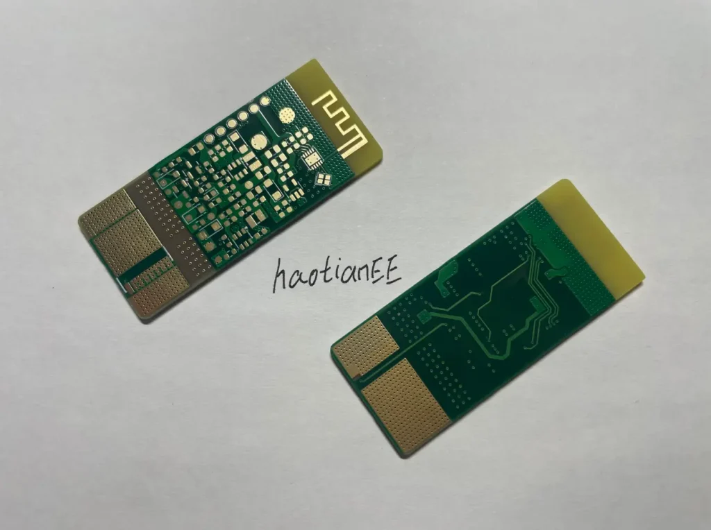
For the PCB, I used a gold-plated finish.
The board is intended to live inside a portable automotive device, so environmental factors such as vibration, humidity, and repeated handling are worth considering.
The gold-plated finish provides good oxidation resistance and electrical contact characteristics, which should help with long-term reliability.
The PCB layout also separates the low-power wireless/control modification rather than a commercial product, I tried to keep the board compact without making the layout unnecessarily complicated section from the higher-current switching section as much as practical.
The high-current path needs to be designed with sufficiently wide copper traces and appropriate thermal considerations, while the wireless section benefits from having a relatively clean power supply and suitable antenna placement.
Since this is ultimately a practical modification rather than a commercial product, I tried to keep the board compact without making the layout unnecessarily complicated.
7. Firmware Programming and Assembly
After PCB fabrication, the next step was programming the wireless controller and assembling the board.
The firmware itself is intentionally simple.
The main task is to wireless controller does not have to care whether the external battery happens receive the wireless command and control the MOSFET switching state.
The overall control flow is essentially:
Wait for remote command
        │
        ▼
Receive valid command
        │
        ▼
Turn MOSFET ON
        │
        ▼
Power output enabled
The board was then assembled and installed into the jump starter for testing.
[PCB programming photo]
Programming the CH570-based control board.
[Assembly photo]
Assembled 2.4GHz remote power switch board.
8. Real-World Testing
The first thing I wanted to verify was the wireless range.
In an outdoor environment, the remote control remained stable at distances of around 100 meters.
For an automotive jump starter, this is already more than sufficient for normal use.
I also tested the board with both 12V and 24V battery systems.
The wide-input architecture allows the same control board to be used across both applications without changing the basic control circuitry.
Another important part of the test was verifying the switching behavior.
The intended sequence is:
- Turn the jump starter output off.
- Connect the positive and negative clamps to the vehicle battery.
- Make sure the connections are secure.
- The MOSFET turns on and connects the jump starter output.
This is fundamentally different from a conventional jump starter where the output is already live while the clamps are being connected.
The main purpose of the modification is therefore to avoid making a live electrical connection at the clamp-to-battery interface.
9. Why Support Both 12V and 24V?
Although most passenger vehicles use 12V electrical systems, 24V systems are common in trucks and other commercial vehicles.
Since portable jump starters are also available for different vehicle types, I wanted the control board to be reasonably versatile.
The input stage therefore accepts approximately 7–24V, while the internal power architecture generates fixed rails for the control electronics and MOSFET gate drive.
This means the wireless controller does not have to care whether the external battery happens to be a nominal 12V or 24V system.
The same PCB can handle both applications within the intended input range.
10. What This Modification Actually Sol the main output disabled while the clamps are being connected, the design aims to reduce the possibility of arcing at the connection does not replace proper battery polarity protection, current protection, fusing, or other safety measures that a what makes these DIY electronics projects interesting. There is no need to turn every project into a commercial product. Sometimes it is simply fun to noticeves
The modification is fairly simple, but it addresses a specific annoyance with conventional jump starters.
The important change is not simply adding a wireless remote.
It is changing the order of operation:
Traditional: connect → electrical contact occurs immediately → possible arcing
This design: power OFF → connect → remote ON → power delivered
By keeping the main output disabled while the clamps are being connected, the design aims to reduce the possibility of arcing at the connection point.
It also means the user does not need to handle a live high-current output while positioning the clamps.
Of course, this board does not replace proper battery polarity protection, current protection, fusing, or other safety measures that a complete jump starter system may require. It is simply a remote-controlled power switching stage.
11. Conclusion
This project started with a relatively small annoyance: the spark that can occur when connecting a conventional jump starter to a vehicle battery.
Rather than redesigning the entire jump starter, I decided to solve the problem by adding a remotely controlled power switch between the battery pack and the output clamps.
The resulting board combines a CH570-based 2.4GHz wireless controller, a MOSFET high-current switch, a 7–24V input stage, and a dedicated 12V gate-drive supply.
The basic concept is simple:
Connect the clamps first, then turn on the power remotely.
The board worked with both 12V and 24V systems, and the wireless link remained stable at around 100 meters in my outdoor testing.
This is not a particularly complicated circuit, but I think it is a good example of how a small hardware modification can solve an annoying real-world problem.
For me, that is also what makes these DIY electronics projects interesting. There is no need to turn every project into a commercial product. Sometimes it is simply fun to notice a problem, design a circuit to solve it, build a PCB, and see whether the idea actually works.
I will continue experimenting with the circuit and may make further improvements to the design in future projects.