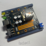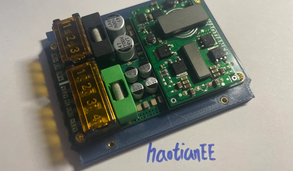
72W Isolated DC-DC Converter for AGV Applications: 38–75V Wide Input, ±12V Output and Planar Transformer Design

Quick Start Guide
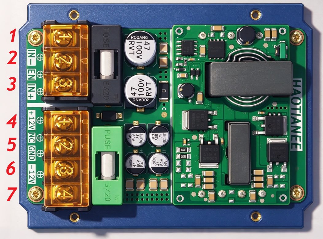
The board interface consists of a 3-pin input connector and a 4-pin output connector. Pin assignments and functional descriptions are provided below.
Input Connector (Pins 1–3)
| Pin No. | Signal Name | Description |
|---|---|---|
| 1 | IN− | Negative input / DC input return |
| 2 | EN (NC) | EN Pin: Pin 2 is internally connected to IN− through a 0Ω resistor. It is reserved for potential future use and must remain unconnected in the current hardware revision. Do not apply any external voltage. |
| 3 | IN+ | Positive DC input |
Output Connector (Pins 4–7)
| Pin No. | Signal Name | Description |
|---|---|---|
| 4 | +12V | Positive output voltage, +12V DC |
| 5 | NC | No internal connection. Leave unconnected. |
| 6 | GND | Output ground / 0V reference |
| 7 | −12V | Negative output voltage, −12V DC |
Important Notes
- Default Startup: The converter is enabled by default and starts automatically when the input supply is applied.
- EN Pin: Pin 2 is internally pulled low to IN−. It is reserved for potential future use and must remain unconnected in the current hardware revision. Do not apply an external voltage.
- NC Pins: Pins marked NC must remain unconnected. Do not connect them to power, ground, or external signals.
- Output Polarity: The output provides dual ±12V DC rails referenced to GND.
Engineering Development Information
- Product Category: Isolated DC-DC Power Converter
- Power Architecture: Active-Clamp Forward Converter
- PWM Controller: Texas Instruments LM5025A
- Transformer Technology: Custom Planar Transformer
- Input Voltage: 38–75V DC
- Output Voltage: ±12V DC
- Output Current: 3A per rail
- Maximum Output Power: 72W
- Development Status: Prototype Testing and System-Level Validation
Board Details
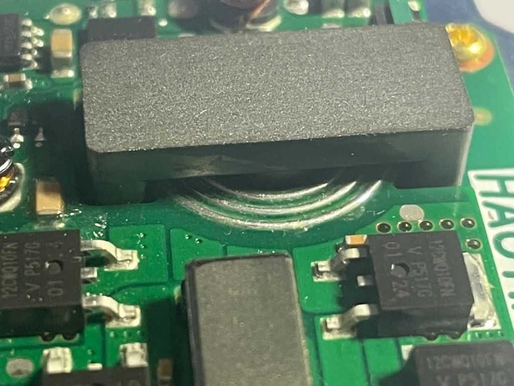
- Quick Start Guide
- Important Notes
- Board Details
- Introduction
- 1. Power Architecture: Wide Input Range and High-Density Isolated Conversion
- 72W AGV Auxiliary Power Converter
- 2. Planar Transformer Design: Mechanical Reliability and Parasitic Optimization
- 3. Electrical Isolation, EMI Immunity and Protection
- 4. PCB Layout: Isolation Clearances, Thermal Management and Signal Integrity
- 5. Testing and Validation: From Prototype to AGV Integration
- 6. Conclusion: A Compact Isolated Power Solution for Industrial AGVs
Introduction
Reliable onboard power is essential for modern Automated Guided Vehicles (AGVs). Industrial PCs, HMI displays, communication interfaces, sensors, and control electronics all depend on a stable auxiliary power supply to maintain continuous operation.
However, designing a reliable power supply for AGV applications presents several challenges.
First, a 16S LiFePO4 battery pack has a relatively wide operating voltage range. Its voltage can reach 58.4V when fully charged and may drop below 40V during heavy-load conditions or battery discharge.
Second, servo motors and motor drives generate substantial electromagnetic interference (EMI), including switching noise, common-mode disturbances, and transient voltage fluctuations. These disturbances can affect sensitive onboard electronic systems if the auxiliary power supply is not properly designed.
To address these challenges, we developed a 72W isolated DC-DC converter based on the Texas Instruments LM5025A PWM controller, specifically designed for AGV auxiliary power applications.
The converter features a wide 38–75V DC input range and dual ±12V outputs, each rated at up to 3A. With a compact PCB layout and a custom-designed planar transformer, the power module is engineered to deliver stable, isolated power in electrically noisy and mechanically demanding industrial environments.
This engineering case study explores the design considerations behind the converter, including topology selection, planar transformer optimization, electrical isolation, protection mechanisms, and PCB layout.
1. Power Architecture: Wide Input Range and High-Density Isolated Conversion
Why a wide input voltage range matters for AGVs
A nominal 48V AGV battery system does not operate at a constant voltage.
For a 16S LiFePO4 battery pack, the voltage can vary significantly depending on its state of charge, load conditions, and operating environment.
A power converter designed only for a narrow input range may experience undervoltage shutdown, output instability, or excessive electrical stress during demanding operating conditions.
Our design addresses this challenge with a 38–75V DC input range, providing additional operating margin for battery voltage fluctuations.
LM5025A-based active-clamp power architecture
The converter uses the TI LM5025A, an active-clamp voltage-mode PWM controller designed for high-efficiency isolated DC-DC conversion.
The active-clamp forward topology provides several important design advantages:
- Improved transformer core reset and utilization.
- Reduced switching losses through optimized active-clamp operation.
- Potentially higher conversion efficiency and power density compared with conventional reset techniques.
- Flexible switching control through programmable timing and synchronization.
The LM5025A integrates essential PWM control functions, including soft start, programmable undervoltage lockout, current limiting, and thermal shutdown. Its two gate-drive outputs control the main power switch and active-clamp switch.
Unlike a fully integrated DC-DC module, this architecture allows the power stage, transformer, switching devices, and feedback network to be optimized around the specific requirements of the AGV application.
Texas Instruments – LM5025A Official Product Page
LM5025A Datasheet – Active Clamp Voltage Mode PWM Controller
Key electrical specifications
72W AGV Auxiliary Power Converter
Input voltage range
38–75V DC
Maximum output power
72W
Positive output
+12V / 3A
Negative output
−12V / 3A
Power topology
Active-Clamp Forward
PWM controller
TI LM5025A
Transformer technology
Planar Transformer
Application
AGV Auxiliary Power
The two output rails are rated at 3A each, corresponding to 72W combined output power under simultaneous full-load operation.
The dual-polarity output configuration is suitable for onboard electronic subsystems requiring both positive and negative supply rails, subject to their grounding and load requirements.
2. Planar Transformer Design: Mechanical Reliability and Parasitic Optimization
The planar transformer is one of the key components of this power module.
Unlike conventional wire-wound transformers, planar transformers use copper traces integrated into multilayer PCBs to form the primary and secondary windings.
This construction provides several advantages for AGV applications.
Improved mechanical robustness
AGVs operate in environments involving continuous vibration, mechanical shock, and frequent acceleration and deceleration.
A PCB-integrated transformer winding structure eliminates many of the mechanical concerns associated with conventional wire-wound assemblies, such as winding movement and mechanical deformation.
The planar construction also provides repeatable manufacturing geometry, making it easier to maintain consistency across production batches.
Reduced leakage inductance
Transformer leakage inductance is an important factor in high-frequency power converter design.
Excessive leakage inductance can contribute to voltage spikes during switching transitions, increasing the voltage stress on MOSFETs and potentially creating additional EMI problems.
The planar transformer allows precise control over winding geometry and the relative positioning of primary and secondary copper layers.
With appropriately designed winding interleaving, leakage inductance can be reduced, helping to improve switching behavior and minimize unwanted voltage transients.
Parasitic capacitance and EMI considerations
Although planar transformers offer excellent control over winding geometry, their interleaved structures can also increase primary-to-secondary parasitic capacitance.
Therefore, transformer optimization requires balancing leakage inductance, parasitic capacitance, insulation requirements, and thermal performance.
For this AGV power supply, transformer design is considered together with the PCB switching-current loops and input/output filtering network.
The objective is not simply to minimize one parasitic parameter, but to achieve a balanced design that supports reliable power conversion and manageable electromagnetic emissions.
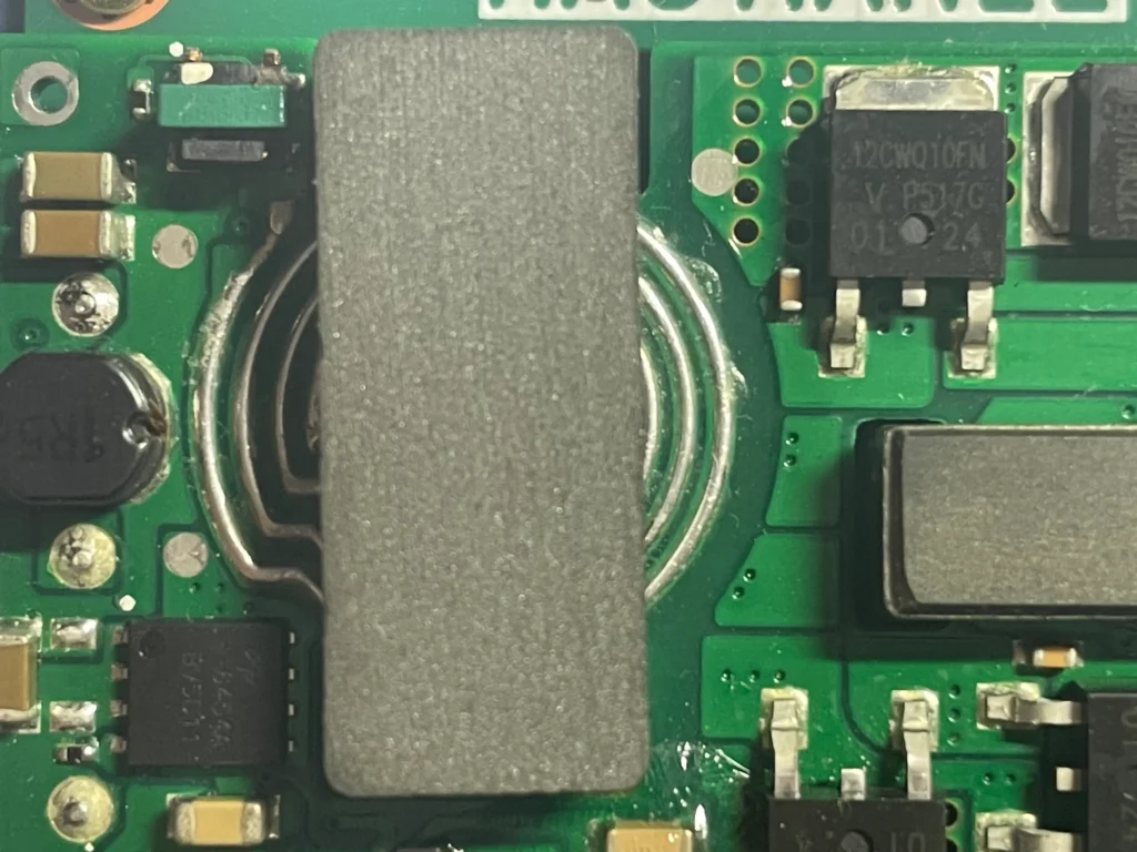
Planar transformer technology used in compact isolated power conversion.
3. Electrical Isolation, EMI Immunity and Protection
Electrical isolation is essential when supplying sensitive onboard electronics from a high-current battery system.
In an AGV, disturbances generated by servo drives, switching devices, and motor cables can propagate through power and ground connections.
An appropriately designed isolation barrier helps prevent direct conductive coupling between the battery-side power stage and the secondary-side electronics.
Reinforced isolation design
The converter uses a custom planar transformer to establish the primary-to-secondary isolation barrier.
The insulation system, transformer construction, PCB creepage distance, and electrical clearance must be designed together to satisfy the intended safety requirements.
The PCB layout reserves an isolation region of at least 8mm between the primary and secondary sides as a design target.
Final compliance must be determined based on working voltage, transient overvoltage, insulation material properties, pollution degree, altitude, and the applicable certification requirements.
Importantly, an 8mm PCB spacing alone does not establish reinforced-insulation certification. The complete transformer and converter assembly must be evaluated as a system.
EMI management in motor-drive environments
Servo drives are major sources of conducted and radiated electromagnetic interference in AGV platforms.
The design therefore focuses on several practical EMI control measures:
- Minimizing high-frequency switching-current loop areas.
- Optimizing transformer winding geometry and parasitic parameters.
- Separating sensitive feedback signals from high-noise switching nodes.
- Providing appropriate input and output filtering.
- Maintaining proper grounding and isolation boundaries.
These measures help reduce unwanted noise coupling into onboard industrial PCs, communication interfaces, and display electronics.
Protection mechanisms
The LM5025A provides several built-in protection and control functions, including:
- Programmable input undervoltage lockout (UVLO).
- Cycle-by-cycle current limiting.
- Programmable soft start.
- Hiccup-mode fault protection with adjustable delays.
- Thermal shutdown.
Additional system-level protection, such as input overvoltage and output overvoltage protection, can be implemented through the appropriate external circuitry where required.
During preliminary short-circuit testing, the converter was subjected to an output short-circuit condition.
The protection response was observed, with the converter entering hiccup-mode operation. Normal operation resumed after the fault was removed.
This protection behavior helps limit the electrical stress associated with downstream load faults.
4. PCB Layout: Isolation Clearances, Thermal Management and Signal Integrity
A 72W isolated DC-DC converter operating from a 48V-class battery system requires careful PCB design.
Component placement, copper geometry, isolation distances, and thermal paths all directly affect electrical performance and long-term reliability.
4.1 Creepage distance and electrical clearance
The PCB is divided into clearly defined primary-side and secondary-side regions.
An isolation boundary of at least 8mm is maintained as part of the design layout.
Within this region, copper traces, ground planes, and other conductive structures are kept away from the isolation boundary to avoid compromising the insulation system.
The design also considers:
- Transformer insulation requirements.
- Primary-to-secondary PCB spacing.
- Conductive contamination risks.
- Mechanical tolerances and manufacturing consistency.
- Applicable reinforced-insulation requirements.
These considerations are particularly important for AGV systems operating in industrial environments where dust, vibration, and temperature variations may affect long-term insulation reliability.
4.2 Thermal management through PCB copper and thermal vias
At full output power, switching losses and conduction losses generate heat throughout the power stage.
To improve heat dissipation, the PCB incorporates strategically positioned copper areas and thermal vias around designated thermal dissipation points.
These structures provide additional thermal paths from heat-generating components into the PCB copper layers.
The layout is optimized to balance:
- MOSFET conduction and switching losses.
- Transformer copper and core losses.
- PCB copper temperature rise.
- Localized thermal concentrations.
- Airflow and enclosure limitations.
During preliminary testing at 25°C ambient temperature and full-load conditions, the component surface temperature rise remained within the design target without requiring an additional heatsink.
Further thermal validation under elevated ambient temperatures and enclosed installation conditions remains part of the planned qualification process.
4.3 Sensitive feedback signal routing
Feedback signals play an important role in maintaining output voltage regulation.
In this design, FBVDD and FBVEE are treated as sensitive feedback nodes.
Their PCB routing follows several principles:
- Keep high-impedance feedback traces as short as practical.
- Place relevant feedback resistors close to the associated IC pins.
- Avoid routing sensitive signals near transformer switching nodes.
- Maintain adequate separation from high-current switching loops.
- Minimize unwanted coupling from noisy power-stage components.
These measures help improve noise immunity and reduce the risk of feedback instability.
5. Testing and Validation: From Prototype to AGV Integration
A reliable power module must be evaluated beyond its schematic and PCB design.
The prototype has completed preliminary testing under the following conditions:
| Test item | Current status |
|---|---|
| Room-temperature power-on test | Completed |
| Room-temperature load test | Completed |
| Output short-circuit protection | Completed |
| Full-load thermal evaluation at 25°C | Preliminary evaluation completed |
| AGV system-level EMC testing | Planned |
| High-/low-temperature cycling | Planned |
| Long-term reliability evaluation | Planned |
The next development stage involves installing the module in a 16S LiFePO4-powered AGV and evaluating its performance under actual operating conditions.
Particular attention will be given to conducted and radiated emissions, transient immunity, battery voltage fluctuations, and thermal behavior inside the enclosed onboard control cabinet.
The results will provide a more complete assessment of the converter’s suitability for long-term industrial operation.
6. Conclusion: A Compact Isolated Power Solution for Industrial AGVs
This 72W isolated DC-DC converter demonstrates an engineering approach to the auxiliary power challenges of modern AGV systems.
By combining the TI LM5025A active-clamp PWM controller with a custom planar transformer and carefully optimized PCB layout, the design addresses the key requirements of wide input voltage operation, dual-polarity power delivery, electrical isolation, EMI management, and thermal performance.
With a 38–75V DC input range and dual ±12V/3A outputs, the module is designed to support sensitive onboard electronics in electrically demanding industrial environments.
Although preliminary load and short-circuit tests have been completed, further EMC evaluation, environmental testing, and system-level validation will be necessary before establishing full application qualification.
Our engineering focus is simple: developing compact, reliable, and application-specific power conversion solutions for next-generation industrial automation and mobile robotics.