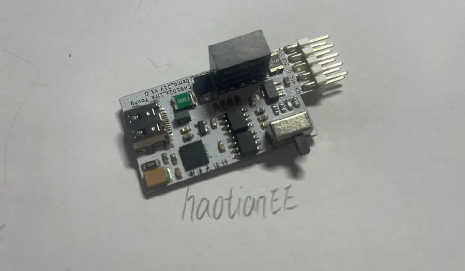
DIY USB-C Isolated USB-to-UART Adapter: CH9102X, Dual Voltage Support, and Full Signal Isolation

- Introduction: Why I Designed My Own Isolated USB-to-UART Adapter
- 1. Why Ordinary USB-to-UART Adapters Have Limitations
- 2. Overall Architecture: Isolated Power and Isolated Signals
- 3. Key Design Advantages
- 4. Applications: When Is an Isolated USB-to-UART Adapter Worth Using?
- 5. Practical Testing and Validation
- 6. Design Considerations and Limitations
- 7. My Experience Using the Adapter
- 8. Conclusion
Introduction: Why I Designed My Own Isolated USB-to-UART Adapter
A USB-to-UART adapter is one of the most frequently used tools on an electronics engineer’s workbench. Whether I am debugging an MCU, capturing boot logs, flashing firmware, or investigating communication issues on an embedded board, a reliable serial interface is almost always essential.
For many everyday tasks, an inexpensive USB-to-TTL adapter based on a CH340 or CP210x bridge is perfectly adequate. Connect the adapter to a computer, connect TX and RX to the target board, establish a common ground, and start communicating.
However, there is one important limitation: most basic USB-to-UART adapters do not provide galvanic isolation between the computer and the target device.
In ordinary low-voltage circuits, this is rarely a problem. But when debugging industrial controllers, battery-powered equipment, automotive electronics, or systems with floating power supplies, the situation can become more complicated.
The computer’s USB ground and the target board’s ground may not be at the same potential. Connecting them directly can create an unwanted ground-current path, introduce common-mode interference, or expose the computer and test equipment to potentially damaging electrical conditions.
That is why I designed my own USB-C isolated USB-to-UART adapter.
The design is built around three key ideas:
- A CH9102X USB-to-UART bridge for the computer interface.
- An isolated power supply to separate the computer-side and target-side power domains.
The target side also supports selectable isolated 5 V and 3.3 V logic supplies, making the adapter more versatile when working with different MCU platforms.
My goal was not simply to add an isolation chip to an existing serial adapter. I wanted to build a practical debugging tool that provides a clear electrical isolation boundary while retaining the control signals needed for firmware programming and MCU reset operations.
In this article, I will explain the design approach, the reasoning behind the isolation architecture, the trade-offs involved, and the checks I would perform before relying on the adapter in a real engineering workflow.
1. Why Ordinary USB-to-UART Adapters Have Limitations


1.1 The Ground Connection Problem
A conventional USB-to-UART adapter typically shares a ground reference between the computer’s USB interface and the target device.
A simplified connection looks like this:
Computer / USB Host
USB ground reference
USB-to-UART Bridge
USB conversion to serial logic
Target MCU Board
Shared ground through the adapter
The key issue is that the target board’s ground is electrically connected to the computer’s ground through the adapter.
If the target circuit is powered from an independent supply, grounded through another instrument, or connected to equipment operating at a different electrical potential, that connection can create an unintended current path.
The consequences depend on the circuit and the fault conditions. Possible problems include:
- Ground-loop currents and communication instability.
- Common-mode noise coupling into the UART interface.
- Unwanted current flowing through USB ground or signal connections.
- Damage to the adapter, computer port, or target hardware if electrical limits are exceeded.
It is important to be precise here: a ground-potential difference does not automatically damage a USB port. The actual risk depends on the magnitude of the voltage difference, available fault current, wiring impedance, protection circuitry, and the path taken by the current.
Nevertheless, directly connecting two systems with incompatible ground references is a risk worth addressing before debugging begins.
1.2 Why UART Signals Alone May Not Be Enough
Some isolated USB-to-UART adapters isolate the main TX and RX communication lines but leave other connections, such as ground, power, or modem-control signals, connected across the isolation boundary.
That can undermine the intended protection.
For example, DTR (Data Terminal Ready) and RTS (Request to Send) are often used by development boards to automate firmware programming or reset an MCU.
A bootloader circuit may use DTR and RTS, together with external transistor logic or capacitive coupling, to control reset and boot-mode pins.
If these control lines bypass the isolation barrier, the adapter may retain an unintended electrical connection between the two domains.
For a design intended to isolate the complete UART control interface, TX, RX, DTR, and RTS should all cross the isolation barrier through appropriately rated isolation channels.
The same principle applies to any auxiliary connection. A power LED, shield connection, programming header, or exposed test point can create an unintended path if the isolation architecture is not considered as a whole.
Galvanic isolation is a property of the complete electrical interface, not merely a feature of the TX and RX pins.
2. Overall Architecture: Isolated Power and Isolated Signals
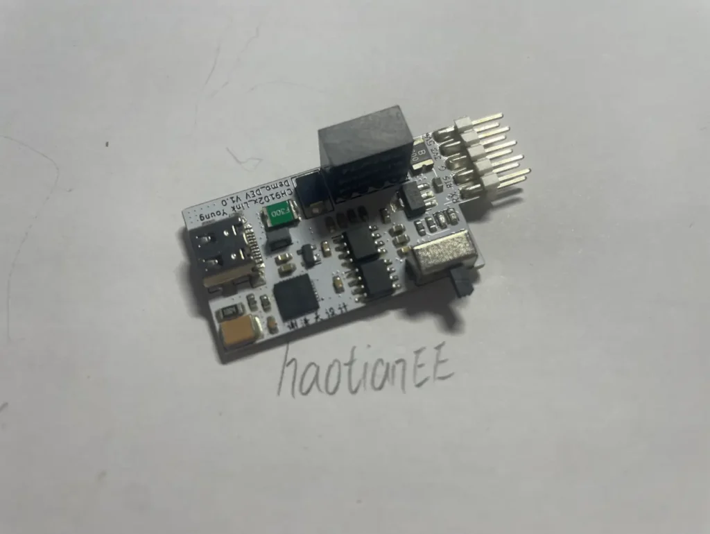
The central design decision was to separate power and signal isolation rather than treating them as a single function.
The adapter has two electrical domains:
- USB side: Connected to the computer and powered from the USB-C input.
- Target side: Electrically isolated from the USB side and used to interface with the external MCU board.
A simplified block diagram illustrates the concept.
USB Side
USB-C Input → CH9102X USB-to-UART Bridge
Computer-side power and ground
Isolated DC-DC
Power-domain separation
Digital Isolators
TX, RX, DTR, RTS
Galvanic Isolation Boundary
No intentional direct conductive connection between the two domains
Target Side
Isolated 5 V Supply → Optional 3.3 V LDO
Selectable target-side logic supply and isolated UART interface
The diagram is conceptual rather than a verified schematic. The exact channel directions, power connections, component pin assignments, and isolation ratings must be confirmed against the actual circuit.
2.1 USB-C Input and the CH9102X Bridge
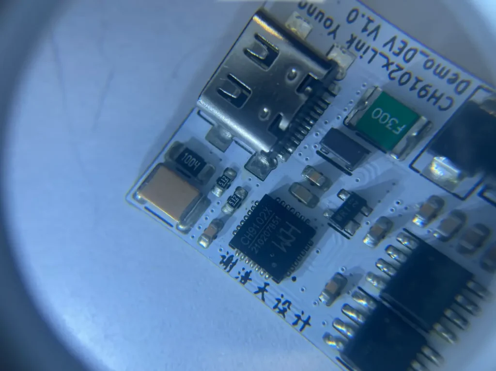
I selected the CH9102X family from WCH (Nanjing QinHeng Microelectronics) as the USB-to-UART interface.
The bridge performs the conversion between USB data and asynchronous serial communication, allowing the computer to exchange data with the target MCU through a familiar serial-port interface.
Using USB-C makes the adapter convenient for modern laptops and development workstations, many of which no longer provide full-size USB-A ports.
However, the connector itself does not guarantee a complete USB-C implementation. A USB-C device designed to operate as a USB 2.0 peripheral must implement the appropriate configuration-channel connections, typically including the required CC pull-down resistors, and follow the relevant USB specifications.
For a robust design, I would also verify:
- USB data-line routing and signal integrity.
- ESD protection at the connector.
- Power-input protection and decoupling.
- Driver compatibility with the intended operating systems.
- The exact USB and UART capabilities of the selected CH9102X variant.
One technical detail deserves attention: USB-to-UART bridge compatibility should not be described as universally driver-free on every operating system. Driver requirements depend on the chip variant, operating system version, and driver implementation. The target computer should be tested with the actual hardware and software configuration.
2.2 Isolated Power: Creating an Independent Target-Side Supply
The second major building block is the isolated DC-DC converter.
On the USB side, the computer supplies nominal 5 V through the USB-C connection. The isolated converter transfers energy to the target side while maintaining electrical separation between its input and output.
A simplified power path is:
5 VUSB→Isolated DC-DC→5 VISO
A low-dropout regulator (LDO) can then derive a 3.3 V rail:
5 VISO→LDO→3.3 VISO
A selector switch can choose which isolated voltage is presented at the target-side power output or logic interface, depending on the actual circuit implementation.
The essential point is that the isolated side has its own ground reference. Its ground does not need to be connected directly to the computer’s USB ground.
That separation can prevent ground-loop currents from flowing through the adapter and can reduce unwanted coupling between the two systems.
However, the isolated supply has finite output power, voltage regulation limits, and parasitic capacitance across the isolation barrier. These characteristics matter when the target circuit is noisy, draws substantial current, or has strict common-mode transient requirements.
The adapter’s isolated supply should therefore be treated as a limited auxiliary supply for the target interface, not as a general-purpose power source for an arbitrary development board.
2.3 Digital Isolation for Four Signals
For the serial interface, I used two digital isolator ICs from 2Pai Semiconductor (荣湃), with two signal channels handled by each device.
The intended signal set is:
| Signal | Typical role | Why isolation matters |
|---|---|---|
| TX | Transmit serial data | Transfers data from the USB bridge to the target |
| RX | Receive serial data | Transfers target data back to the computer |
| DTR | Modem-control signal | May be used for automatic MCU reset |
| RTS | Modem-control signal | May participate in bootloader or reset control |
The exact direction of each channel depends on the circuit implementation. TX and RX are named from the perspective of their respective endpoints, so it is important to verify which side of the isolator drives each signal.
Using dedicated digital isolators for all four signals avoids the design weakness of isolating only the main data lines while leaving control signals electrically connected across the boundary.
This is particularly useful for development boards that rely on DTR and RTS to automate reset and firmware-download sequences.
Digital isolators also introduce propagation delay, channel-to-channel skew, and finite common-mode transient immunity. For ordinary UART debugging, these effects are often manageable, but they should still be checked against the intended baud rate and the timing requirements of the target interface.
3. Key Design Advantages
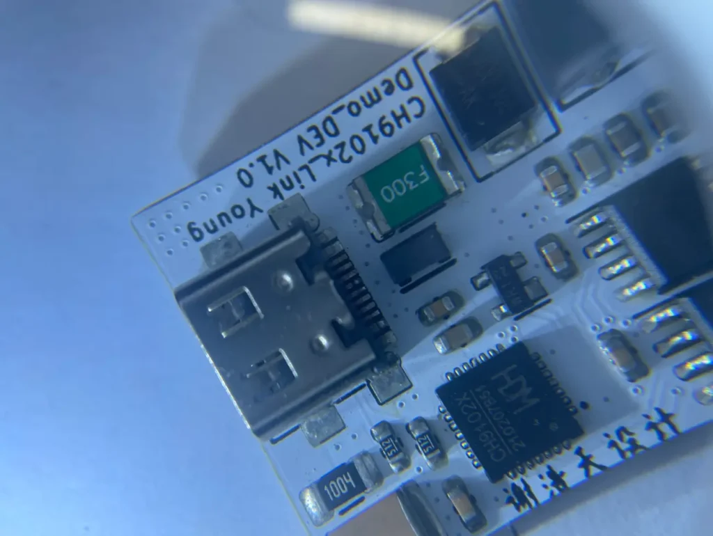
3.1 USB-C Connectivity
A reversible USB-C connector makes the adapter easier to use with current laptops and development systems. It reduces dependence on older Micro-USB cables and USB-A adapters, provided the board implements the required USB-C connections correctly.
3.2 Independent Power and Signal Isolation
The isolated DC-DC converter separates the power domains, while digital isolators separate the UART communication and control signals. Both are needed to achieve the intended architecture without an unintended conductive bypass.
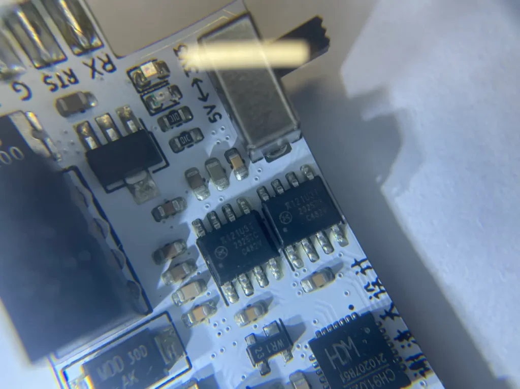
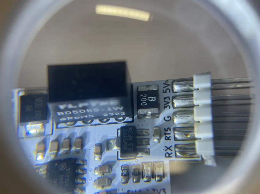
3.3 Dual 5 V / 3.3 V Target-Side Voltage Selection
The isolated 5 V supply and regulated 3.3 V rail provide convenient options for common MCU logic levels. The selected voltage must match the target board’s electrical requirements.
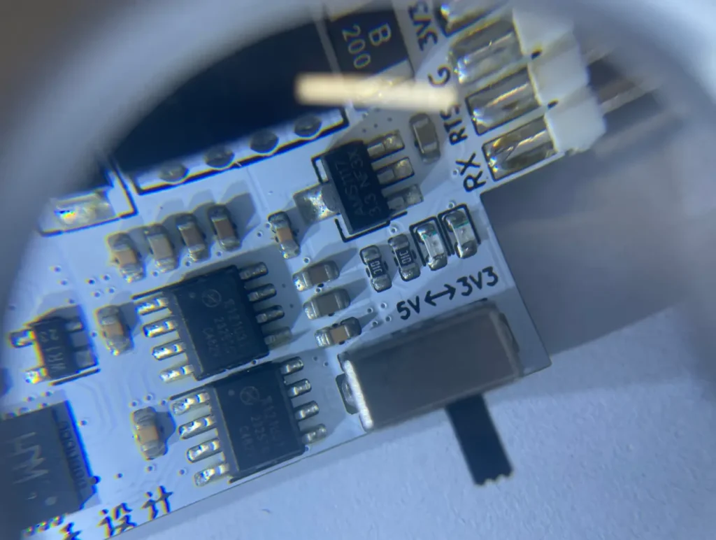
3.4 DTR and RTS Support
Keeping the control signals isolated makes the adapter more suitable for development boards that use automatic reset or boot-mode control during firmware flashing.
Why I Prefer a Complete Isolation Architecture
In a debugging tool, convenience matters, but so does consistency.
If the primary data signals are isolated while another signal creates an unintended connection between the two ground domains, the protection may not work as intended.
By treating the power path and all relevant signal paths as separate design problems, it becomes easier to define the isolation boundary and evaluate whether the finished PCB actually meets its requirements.
That said, a complete isolation architecture should not be confused with an unconditional guarantee against damage. The final protection level depends on the ratings of the isolation components, PCB creepage and clearance, connector layout, enclosure, and all external connections.
4. Applications: When Is an Isolated USB-to-UART Adapter Worth Using?

4.1 Industrial Control Boards
Industrial equipment often contains several power domains, switching converters, motors, and long cable connections.
These environments can produce ground-potential differences and common-mode disturbances that complicate serial debugging.
An isolated adapter can help prevent the computer’s USB ground from becoming an unintended current-return path through the target equipment.
4.2 Battery Systems and Energy Storage
Battery-management systems and energy-storage electronics may contain multiple voltage domains and circuits referenced to different points in the system.
An isolated USB-to-UART adapter can be useful when debugging a low-voltage controller that must remain electrically separated from the computer.
However, an isolated UART adapter is not a substitute for appropriately rated high-voltage isolation, measurement equipment, or safe working procedures. Never connect a low-voltage debugging adapter directly to a high-voltage battery domain unless the complete interface has been specifically designed and rated for that application.
4.3 Automotive Electronics
Automotive controllers may experience switching noise, transient disturbances, and differences in ground potential between connected equipment.
Isolation can reduce unwanted conductive paths during development and testing.
Nevertheless, automotive transient protection, load-dump conditions, and electrical safety requirements are separate design issues. A small USB-to-UART adapter should not be treated as an automotive-rated measurement interface without appropriate qualification.
4.4 Floating or Independently Powered MCU Boards
A target board powered from a separate supply may have a ground reference that differs from the computer’s ground.
Isolation is particularly useful when the objective is to capture logs or flash firmware without intentionally bonding the two grounds through the serial interface.
4.5 When You Probably Do Not Need Isolation
For a simple 3.3 V or 5 V MCU development board powered from the same USB-connected computer, a conventional USB-to-UART adapter is usually sufficient.
Isolation adds cost, board area, power consumption, and propagation delay. If the target and host share a suitable ground reference and there is no meaningful risk from ground loops or electrical transients, an ordinary adapter may be the more practical choice.
The goal is not to isolate everything by default. It is to use isolation where the electrical environment justifies it.
5. Practical Testing and Validation
A hardware design is not complete when the schematic looks correct. It needs to be verified under realistic operating conditions.
For this adapter, I would divide validation into five areas.
5.1 Verify the Isolation Barrier
With the adapter disconnected from external equipment, verify that the USB-side ground and target-side ground do not have an unintended direct conductive connection.
A continuity check is a useful initial screen, but it does not establish a certified isolation rating or prove performance under high voltage.
The actual isolation rating must be supported by component specifications and PCB construction. Creepage distance, clearance, pollution degree, material group, and operating voltage all matter when assessing insulation requirements.
5.2 Verify Both Output Voltages
Measure the target-side output with a suitable meter under both switch positions.
Check:
- The nominal 5 V output.
- The nominal 3.3 V output.
- Startup behavior and voltage settling.
- Output regulation under the intended load.
- Temperature rise and converter stability.
The 3.3 V LDO must have adequate thermal margin. If the target-side load draws significant current, its power dissipation can be approximated as:
PLDO≈(Vin−Vout)Iout
For a 5 V input, 3.3 V output, and 100 mA load:
PLDO≈(5−3.3)×0.1=0.17 W
That is 170 mW of dissipation before accounting for other losses. Whether the package can handle it depends on the PCB copper area, thermal resistance, ambient temperature, and regulator specifications.
5.3 Test UART Communication at Different Baud Rates
Verify basic transmit and receive operation at the baud rates required by the intended applications.
Useful tests include:
- Repeated transmission of known data patterns.
- Long-duration logging.
- Operation at the highest intended baud rate.
- Recovery after USB disconnect and reconnect.
- Behavior when the target supply is switched on and off.
For higher baud rates, signal integrity, digital-isolator propagation delay, and edge quality should be evaluated together rather than assuming that a working low-speed connection guarantees reliable operation at every supported rate.
5.4 Test DTR and RTS Control
If the target development board uses DTR or RTS for reset or bootloader entry, verify the complete programming sequence.
Confirm the signal polarity, timing, and transitions at the target side. Different bootloader circuits use different arrangements, so successful UART data transmission alone does not prove that automatic reset will work correctly.
5.5 Evaluate Noise and Isolation Performance
Where suitable equipment is available, evaluate the adapter under the expected electrical environment.
Potential measurements include:
- Ground-to-ground leakage or insulation behavior under an appropriately designed test procedure.
- Common-mode transient immunity, where relevant to the application.
- Conducted and radiated noise.
- Target-side supply ripple.
- UART error rates under representative interference conditions.
High-voltage insulation testing should only be performed with equipment, procedures, and component ratings appropriate to the intended isolation level. An arbitrary high-voltage test can damage components or create a safety hazard.
Important: The design description establishes the intended architecture, not independently verified test results. Actual performance figures, isolation voltage, baud-rate limits, and measured error rates should only be published after they have been measured and documented.
6. Design Considerations and Limitations
Even a well-designed isolated adapter has limitations.
Isolation voltage is not determined by the digital isolator alone. The DC-DC converter, PCB spacing, connectors, solder mask assumptions, and all other paths across the boundary contribute to the overall design.
USB-C does not automatically imply higher performance. It improves connector convenience, but the USB implementation still needs appropriate electrical protection and routing.
A 5 V or 3.3 V selection switch does not make every MCU compatible. Some MCUs use lower-voltage I/O, have strict input thresholds, or are not tolerant of signals at the selected voltage. Check the target device’s datasheet before connecting it.
The isolated supply has limited capacity. It is intended to support the adapter’s target-side interface and modest auxiliary loads within its rating, not necessarily to power a complete development board.
Isolation does not replace safe high-voltage procedures. If the target system contains hazardous voltages, verify the entire measurement setup, including programmers, oscilloscopes, power supplies, USB connections, and other peripherals.
These are not reasons to avoid isolation. They are reasons to design it deliberately and validate it properly.
7. My Experience Using the Adapter
After the prototype was assembled, I used it to capture serial logs and debug MCU firmware across multiple projects.
The main advantage was workflow consistency. Instead of reaching for a different adapter whenever the target board used a different logic voltage or required automatic reset, I could use the same tool and select the appropriate target-side supply.
The four-channel isolation arrangement was also important for development boards that rely on DTR and RTS during firmware programming. Isolating those signals along with TX and RX allowed the control interface to remain within the intended isolation architecture.
For day-to-day debugging, I found the combination of USB-C connectivity, an isolated supply, and selectable 5 V / 3.3 V logic levels particularly practical.
However, these observations should be understood as design and usage experience rather than a substitute for quantified laboratory results. A production-quality design should document its actual voltage accuracy, maximum load, supported baud rates, isolation specifications, and performance under electrical disturbances.
That documentation is especially valuable if the design will be shared with other engineers or released as an open hardware project.
8. Conclusion
A conventional USB-to-UART adapter is sufficient for many development tasks, but it is not always the right tool when the computer and target circuit operate in different electrical environments.
For my design, I combined a CH9102X USB-to-UART bridge, an isolated DC-DC converter, digital isolation for TX, RX, DTR, and RTS, and selectable isolated 5 V / 3.3 V target-side power.
The resulting architecture addresses three practical needs:
- Electrical separation between the computer and target power domains.
- Isolation of the UART data and control signals.
- Convenient compatibility with common 3.3 V and 5 V MCU interfaces.
The broader lesson is that isolation should be treated as a system-level design requirement rather than a single component choice.
When debugging industrial controllers, battery systems, automotive electronics, or independently powered hardware, understanding the ground-current paths and isolation boundary can make the difference between a reliable development setup and an avoidable electrical problem.
For ordinary low-voltage projects, a basic adapter remains a perfectly reasonable choice. For more demanding environments, a properly designed and validated isolated USB-to-UART interface is a useful addition to any hardware engineer’s workbench.